Anticipating the eventual construction of the viaduct, City staff had begun survey work in 1911 to determine existing conditions, and to establish base lines and bench-marks so that they would be ready to start as soon as the viaduct construction was approved. Early in 1912 they began to test the earth in the valley and concluded that the soil for a considerable depth was unsuitable for carrying the heavy loads of the viaduct. In order to find bedrock, they did boring tests to a depth of 30 to 40 ft. in most instances, with the deepest excavation being 47 ft. below the level of the Don Valley.
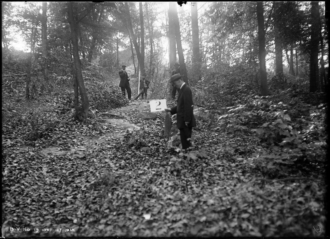
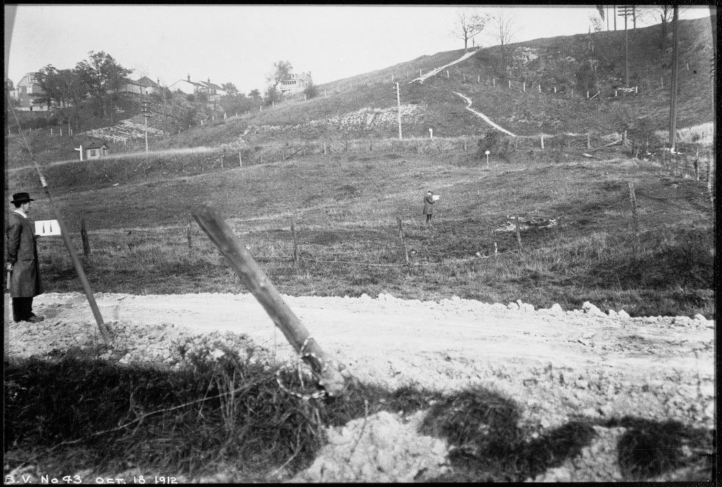
Photographs of general conditions like these proved invaluable to the surveyors, who also took 14,000 elevations resulting in extremely detailed contour maps of the construction site.
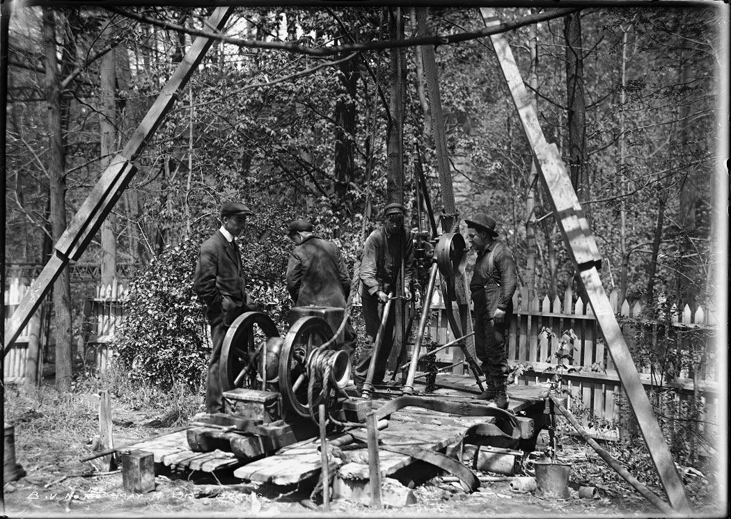
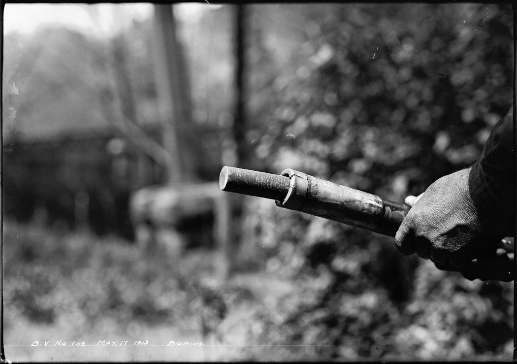
Soil samples were taken by using boring machines, which drilled down through the layers of soil. The core samples were analyzed, and the data told the engineers how far down to excavate to reach bedrock.
It was not only the location of the bedrock that would influence the design of the viaduct, since the Don River, two railway rights-of-way, and Don View Avenue, also had to be accommodated. Additionally, the consulting architect Edmund Burke (1850-1919) naturally wished to maintain a symmetry in the main spans.
Eventually the four centre piers of the Don section were set on solid rock, while the rest were on spread footings on hard, dry clay foundations varying from 10 to 14 ft. below the surface of the ground.
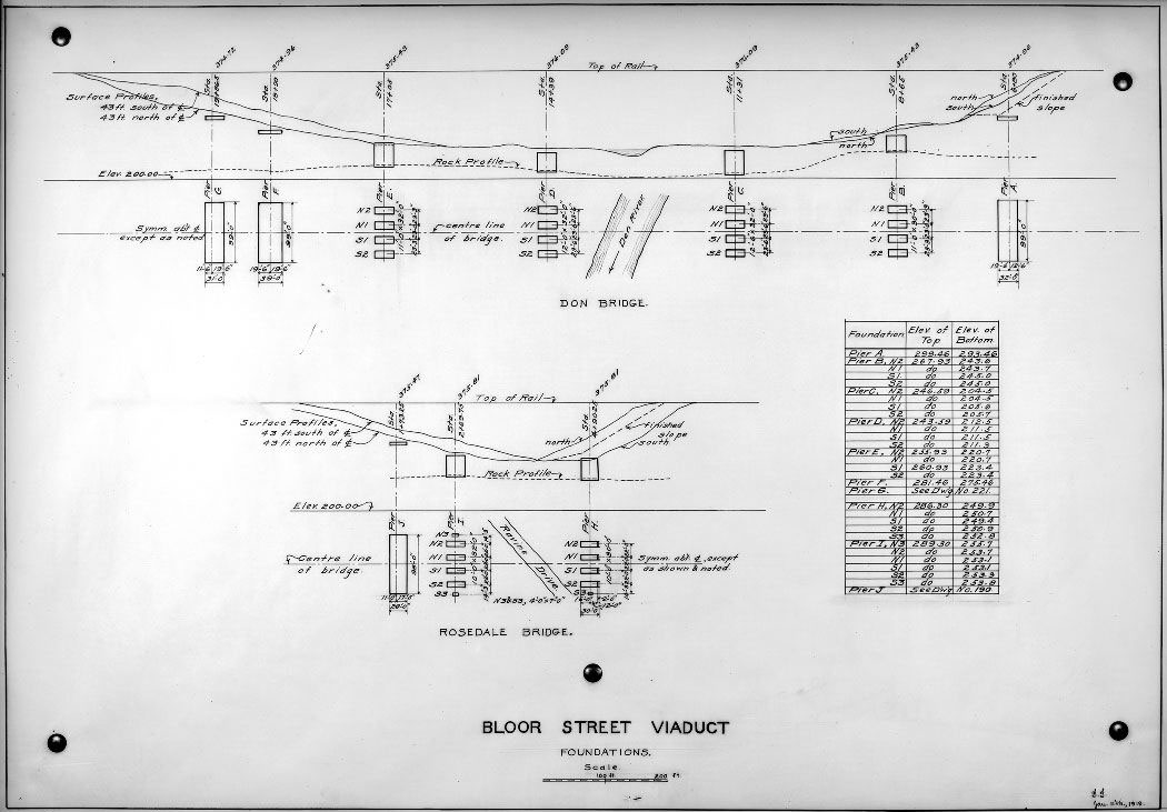
Piers B, C, D and E in the Don Section, and piers H and I in the Rosedale section all rest on bedrock. The piers are lettered from the east to the west, with A through F over the Don Valley, and H through J over the Rosedale Valley. Construction started with pier D, located on the west side of the Don River.
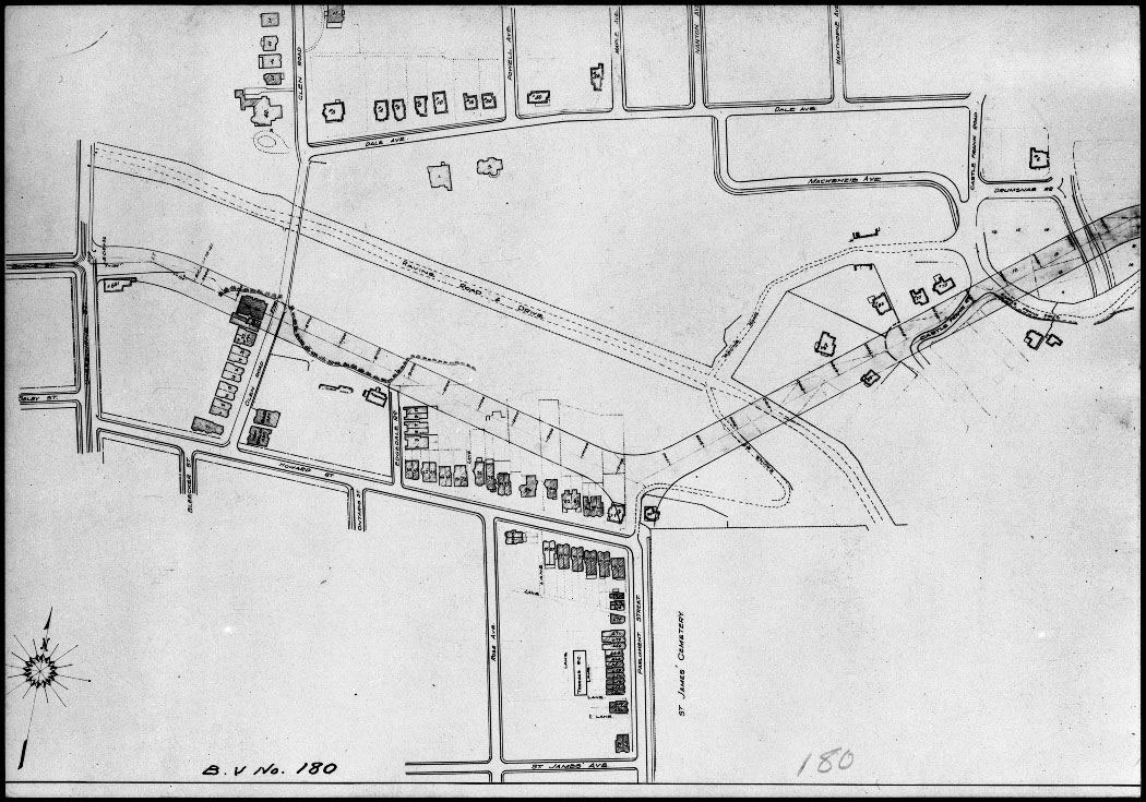
In this general survey of the Bloor and Rosedale sections, one can see the distinctive Y shape created by the necessity to skirt around the Rosedale Ravine. The span of piers H and I in the Rosedale Section crosses over the Rosedale Valley Road, and the Bloor Section is on a man-made embankment to the south of the valley. When travelling this route today, between Sherbourne Avenue and Castle Frank, one is hardly aware that the roads underneath are also part of the viaduct.
Construction work on the viaduct was extensively documented by photographer Arthur Goss (1881-1940), who was employed by the Department of Public Works, Photography and Blue Printing Section, from 1911 to 1940. Goss’s magnificent photographs capture the day-to-day progress of the construction, and his meticulous care in putting dates and titles on his glass plate negatives allows us to see the astonishing speed with which the viaduct was built. There are over 800 Goss images documenting the planning and construction of the viaduct in the Archives’ collection. The following is a small selection chosen to illustrate the progress of the work on the three phases of the viaduct.
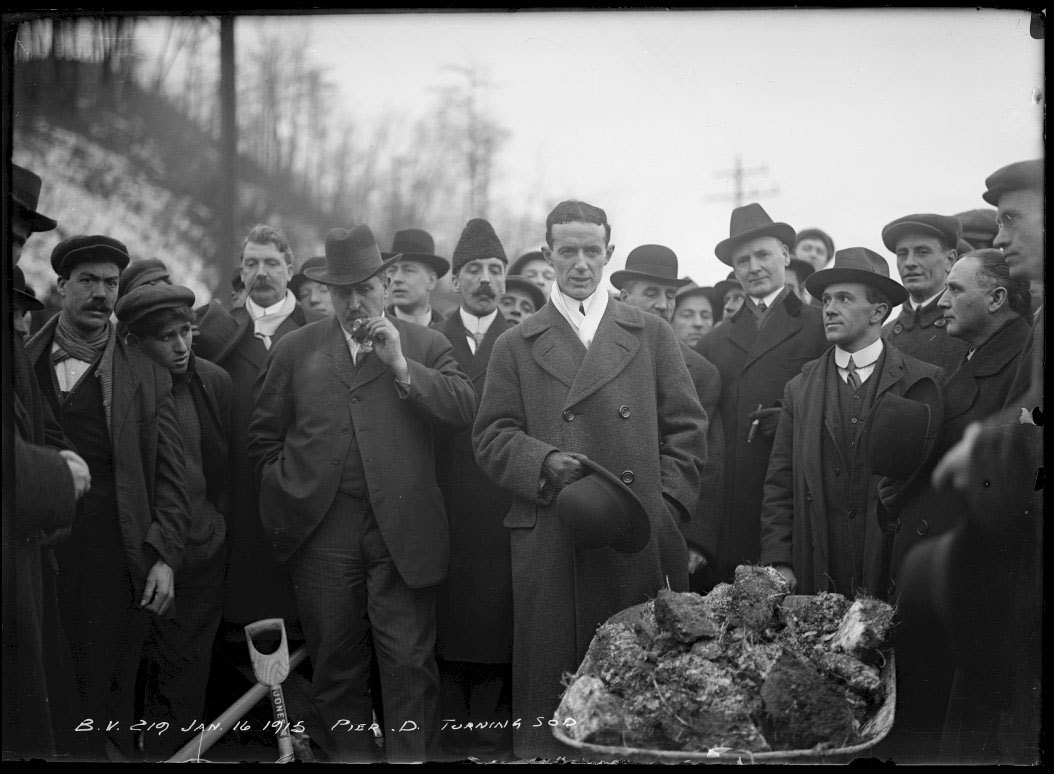
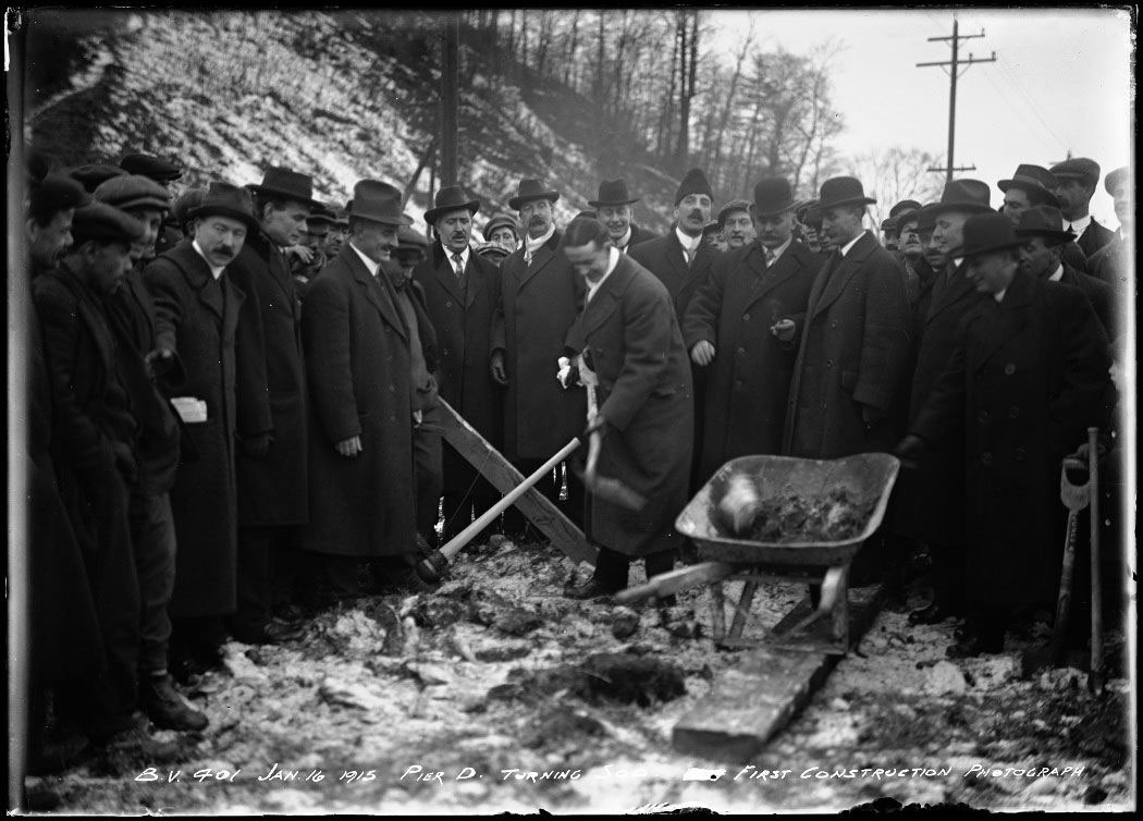
The construction of the viaduct officially began with the sod-turning ceremony presided over by newly-elected Mayor T.L. Church on January 16, 1915. Mayor Church is the man with the bowler hat in his hand (left) and hoisting the shovel (right).
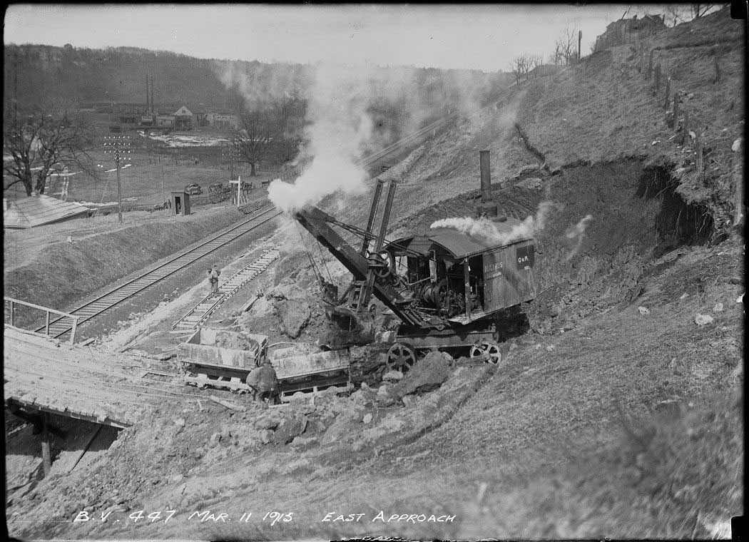
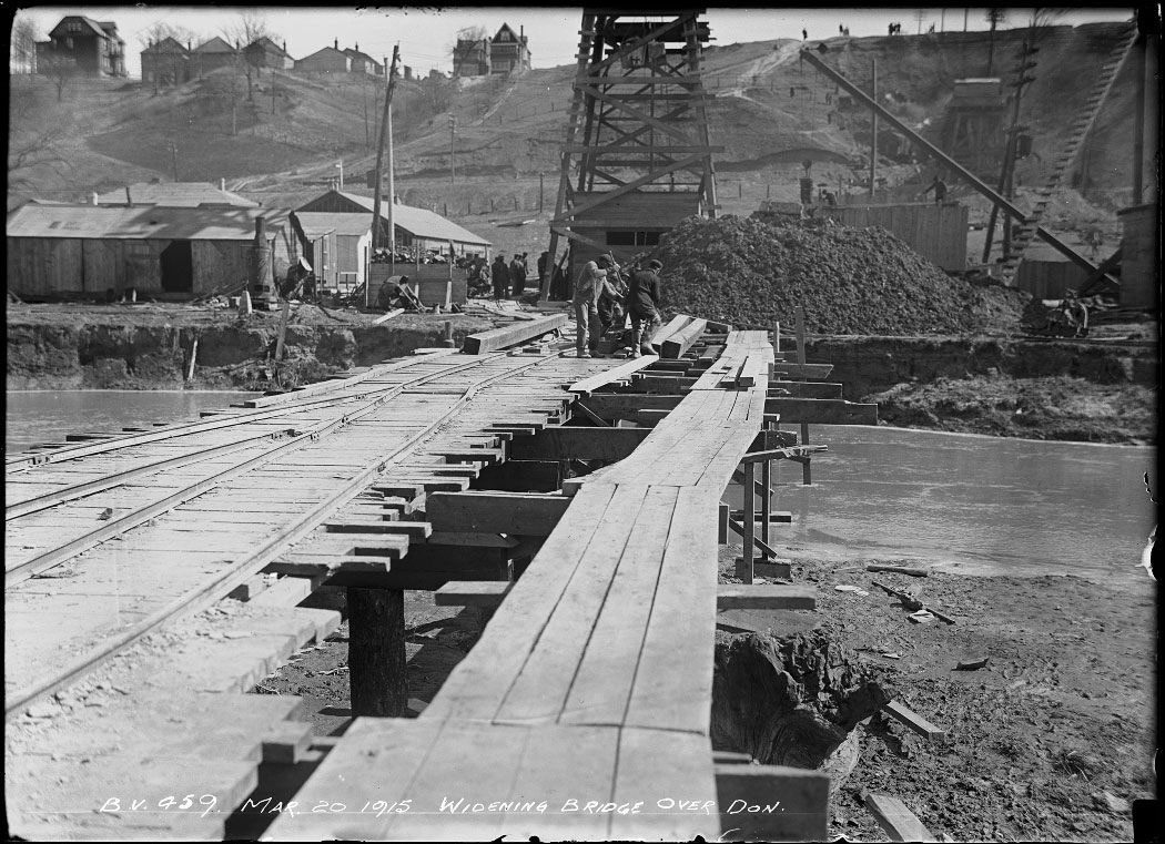
The image on the left shows a full-swivel steam shovel at work doing excavation at the east approach, close to Danforth Avenue. This photo and the one on the right include the temporary bridges constructed over the Don River and the railway tracks. These were used to support tracks to facilitate the removal of excavated materials.
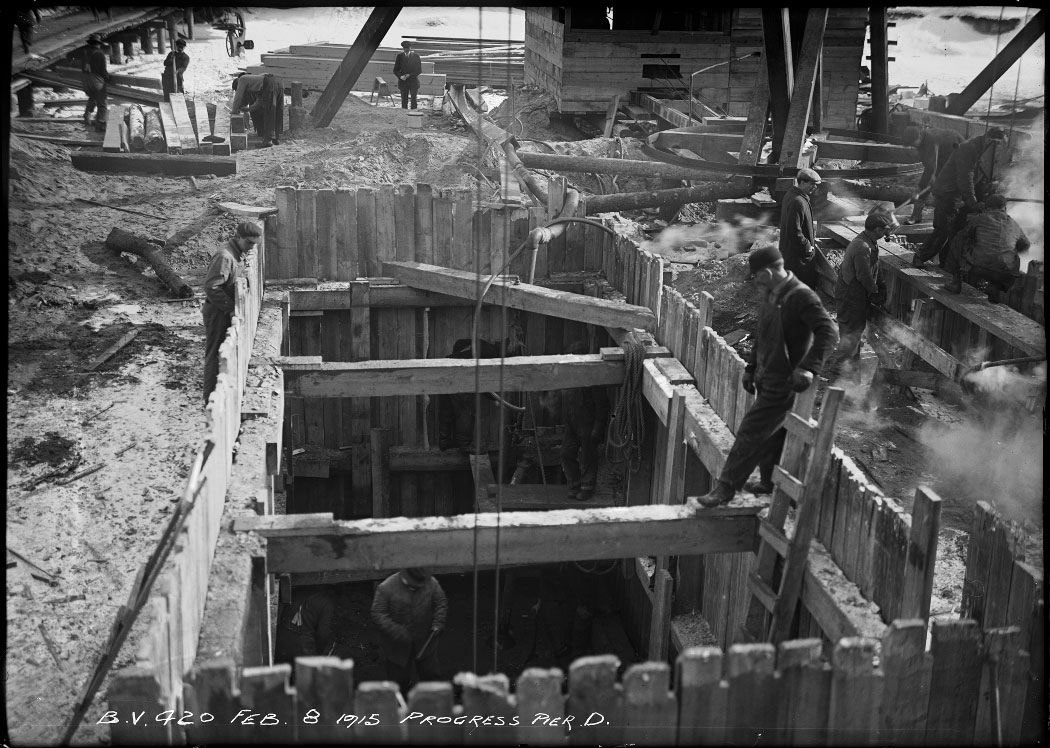
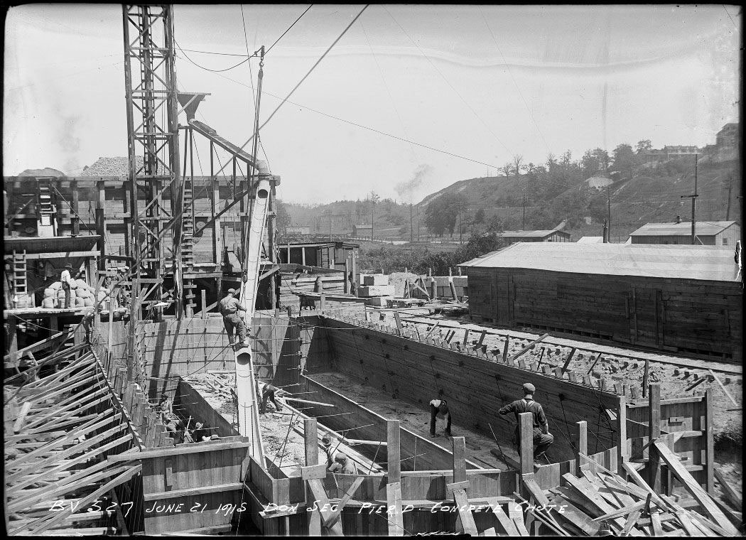
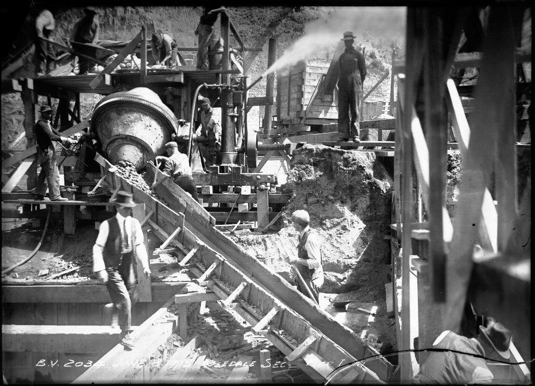
Wooden sheeting kept soil and water out so that excavation of the piers could be done down to bedrock. The sheeting was then left in place when the concrete foundations were poured. In some cases, steel sheeting was used instead of wood. To assist in the delivery of concrete, the contractors erected elevator towers with concrete mixers nearby. From the mixers, concrete was fed into the tower hoppers, and then lines of steel chutes delivered the concrete to the piers. The workers directed or shoveled the concrete to where it was required.
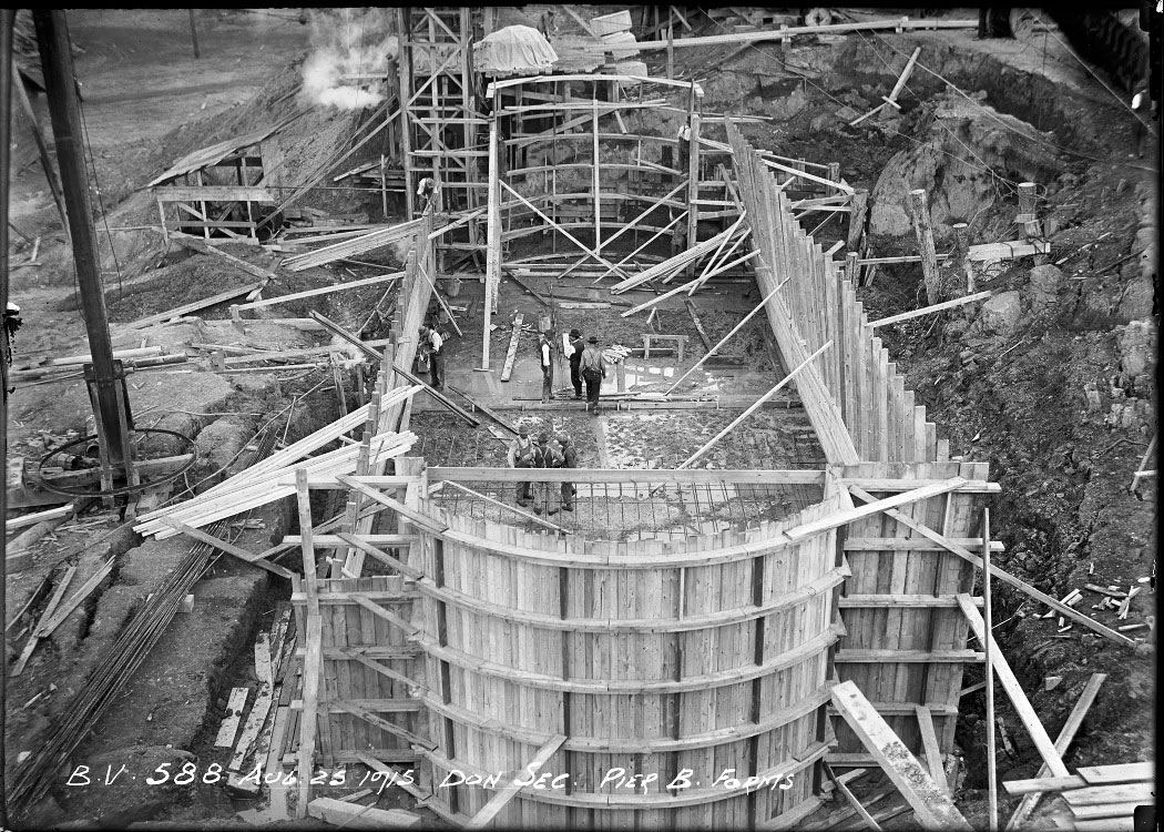
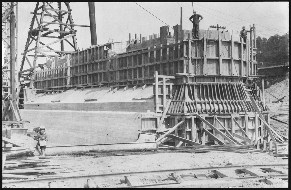
At this point the foundations for the piers are completed, and the men are working on the above-ground forms for the piers. The curve of the pier ends can be seen clearly. The boy in the photo on the right is a surprise; one wonders who would have brought a child to such a busy work site.
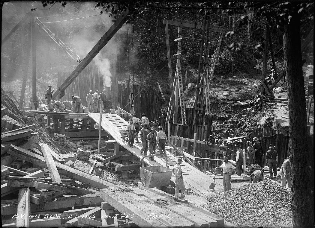
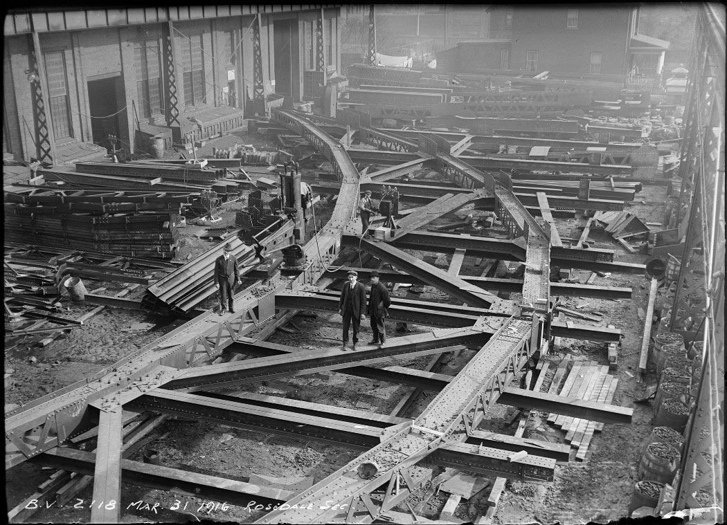
The sheer complexity of such a project, and the large number of skilled workers on the job is evident in this progress photo of work on pier E.
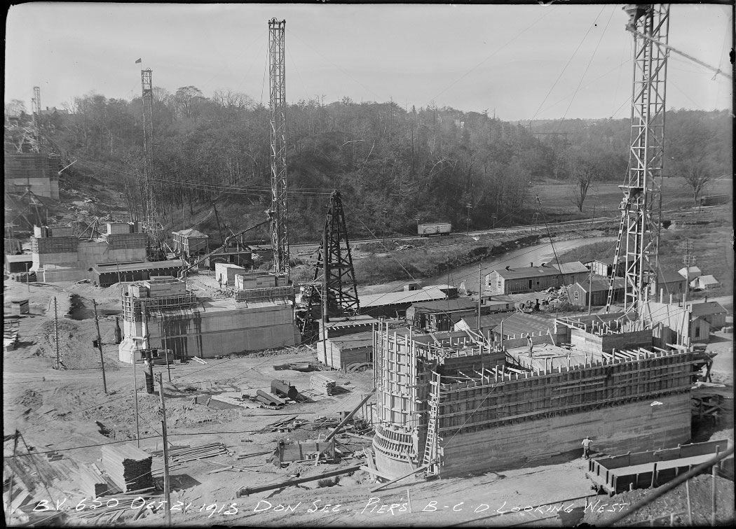
In this view looking west one can see the incredible amount of progress made in only nine months since the sod-turning ceremony on January 16, 1915.
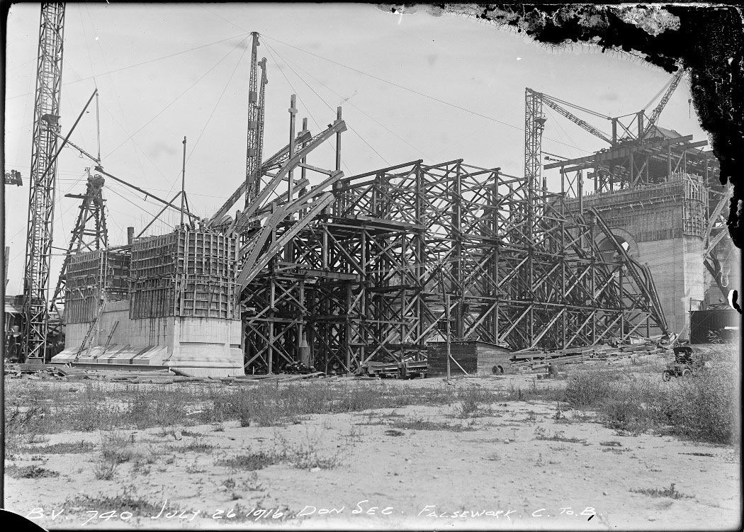
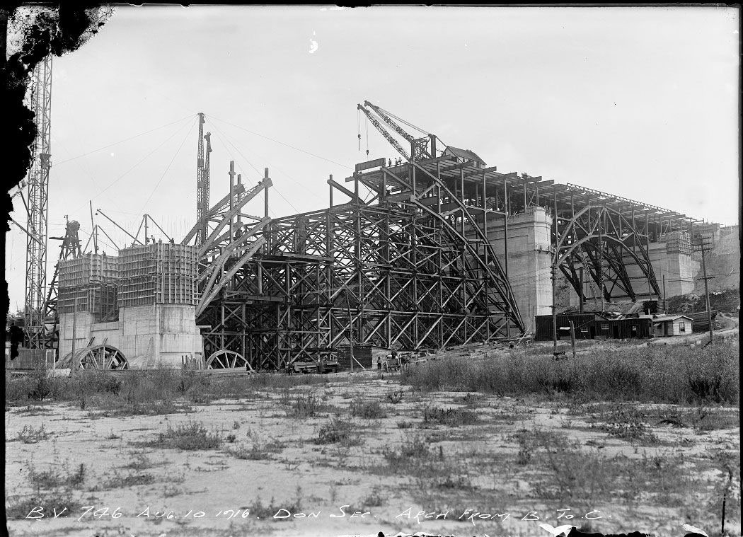
The timber falsework between piers B and C has been erected. This falsework was the temporary structure used to support the steel arches until they were completed and could support themselves. The steel members of the arches on the viaduct were riveted together. Rivets have largely been replaced in modern bridge construction by welding or high strength bolts. In the photo on the right, the steel arches are in place between piers A and B, and the falsework has been removed. A temporary deck has been built which allows for cranes to place the steel members of the arch between piers B and C.
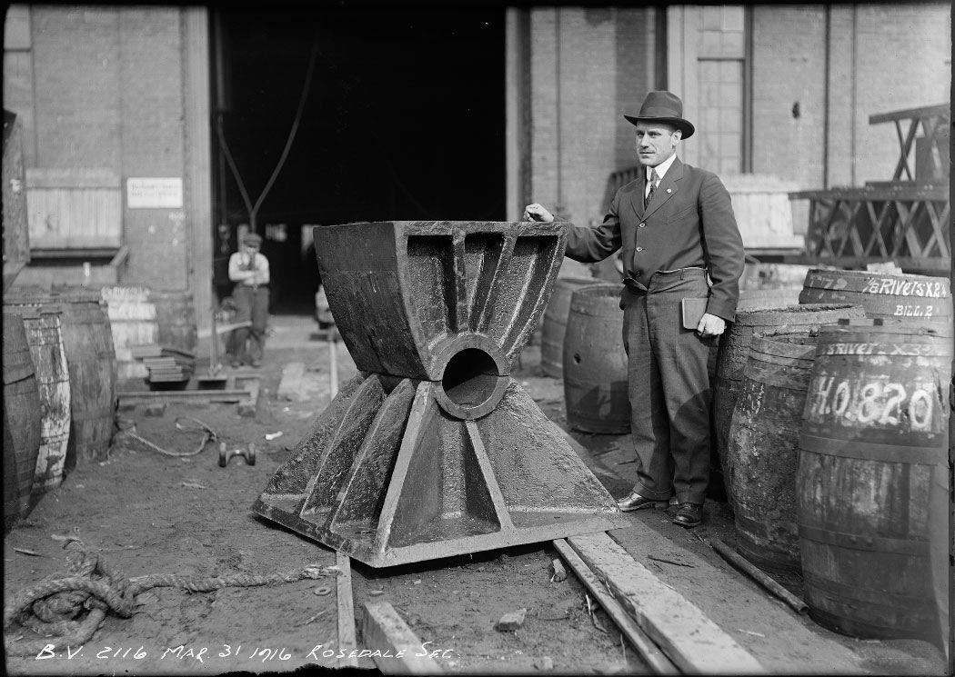
Cast bearings such as the one shown on the left were used at the bases of the steel arch ribs. The bearings rest on granite blocks that are embedded in the concrete.
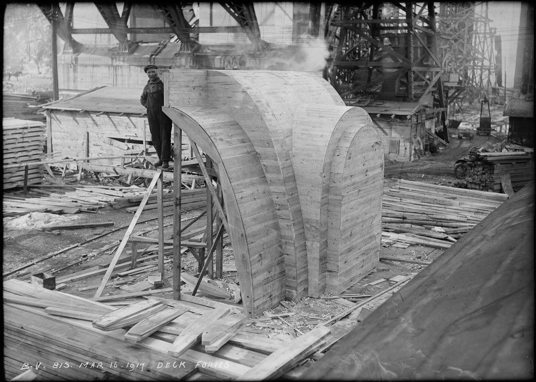
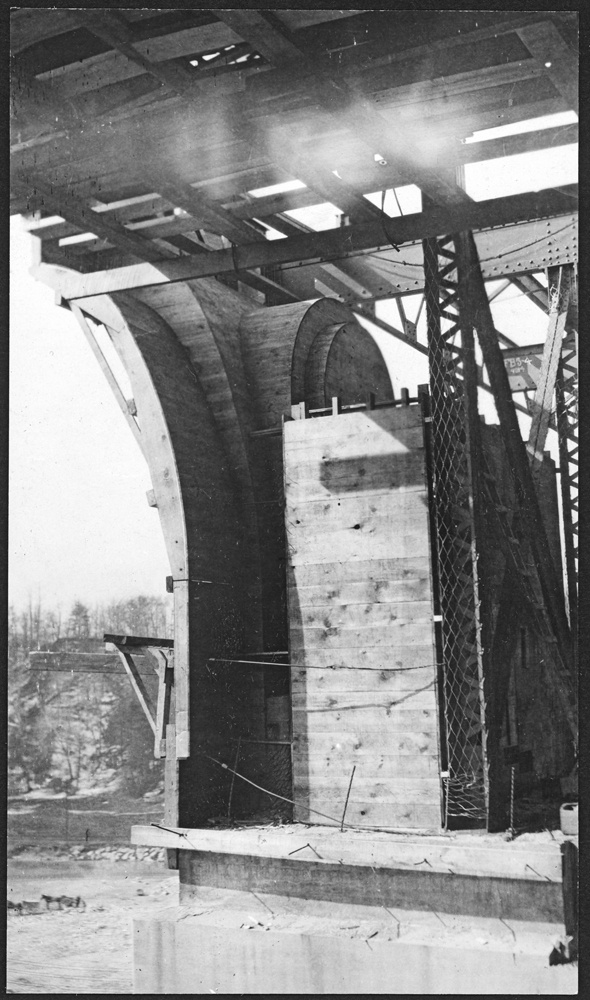
On the left is a wooden form being built in the carpenter shop yard at the construction site. The forms were used to provide a mold for the concrete so that it could take on a decorative shape. This decoration was used on piers B, C, D, and E, above the subway level floor. The finished cast concrete form can be seen in place in the photo on the right.
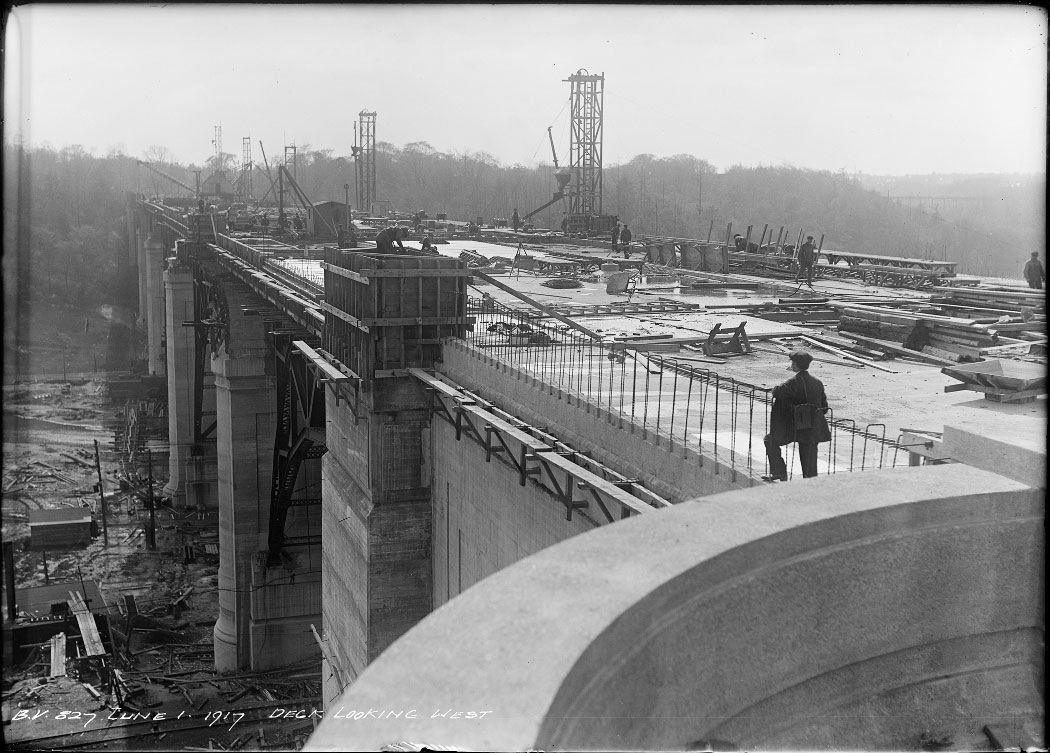
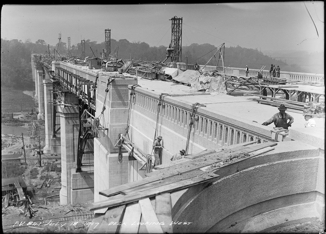
Work progresses on the deck of the Don Section. The finished width of the viaduct would be 86 ft., with 64 ft.-6 in. between the sidewalk curbs. In the photo on the right, the decorative railings of the parapet are in place, and workers on rather precarious-looking platforms 130 ft. above the ground are polishing up the concrete surfaces and the massive pier tops.
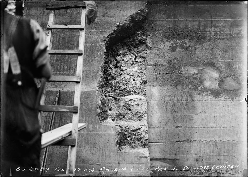
Work on the Rosedale and Bloor sections was happening concurrently with the construction of the Don Section. The image on the left gives a close-up view of the complicated and labour-intensive nature of concrete work, while the one on the right shows that not everything on the project went smoothly. This defective concrete on pier J had to be replaced.
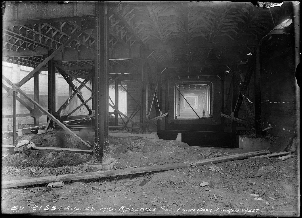
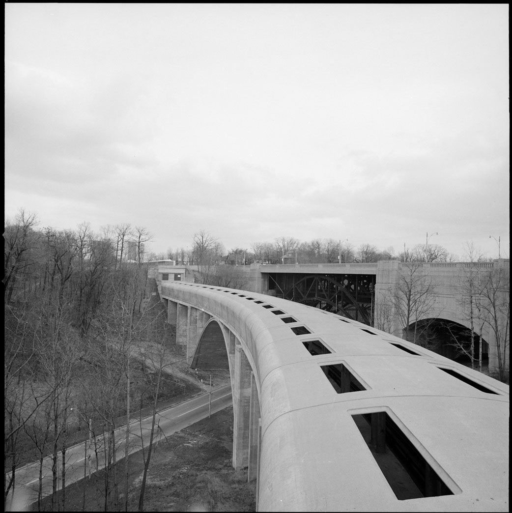
A subway deck was situated underneath the road deck in both the Don and Rosedale sections. Having the subway deck already in place in the Don Section saved a great deal of money when the Bloor-Danforth subway line was built in the 1960s. However, engineers found that the curves in the Rosdale section were too sharp for safe operation of the trains. Instead, a separate covered subway bridge was designed by John B. Parkin and Associates with De Leuw Cather Canada, and installed in 1966. The photo on the right shows the new bridge in 1967, with the Rosedale section of the viaduct just behind.
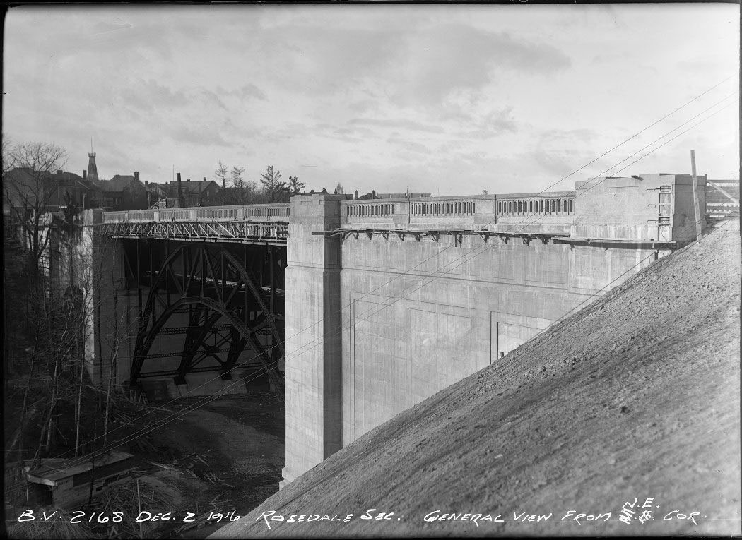
There was only one major span in the Rosedale Section, between piers H and I. The contractor, the Dominion Bridge Company, assembled the steel arches on the ground without falsework before they were hoisted into place. This arched span is 190 ft. long, crossing the Rosedale Valley Road at a height of 90 ft. The steep sides of the valley are clearly seen in the photo on the right.
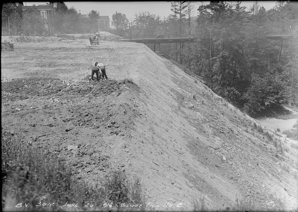
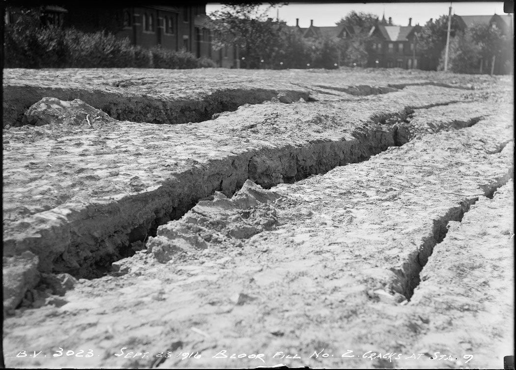
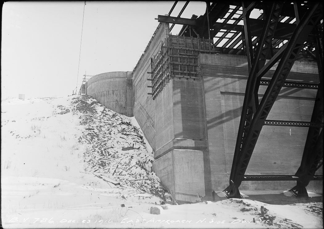
Unlike in the Rosedale Section, the steep sides of the Bloor Section were created by man. Massive amounts of fill were used to create the terrace or embankment which carried the most westerly section of the viaduct between Parliament and Sherbourne streets. In the view on the left, the photographer is looking west and the Glen Road Bridge over the Rosedale Ravine is seen in the distance. On the right, the fill is settling, and cracking in the process. While the Rosedale Section was open for traffic in October of 1917, and the Don Section was open a year later, the Bloor Section opening was delayed until August 23, 1919, largely because of waiting for the fill to settle.
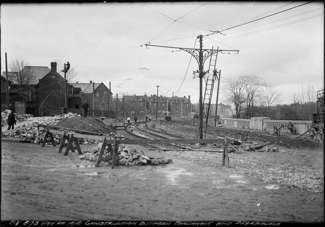
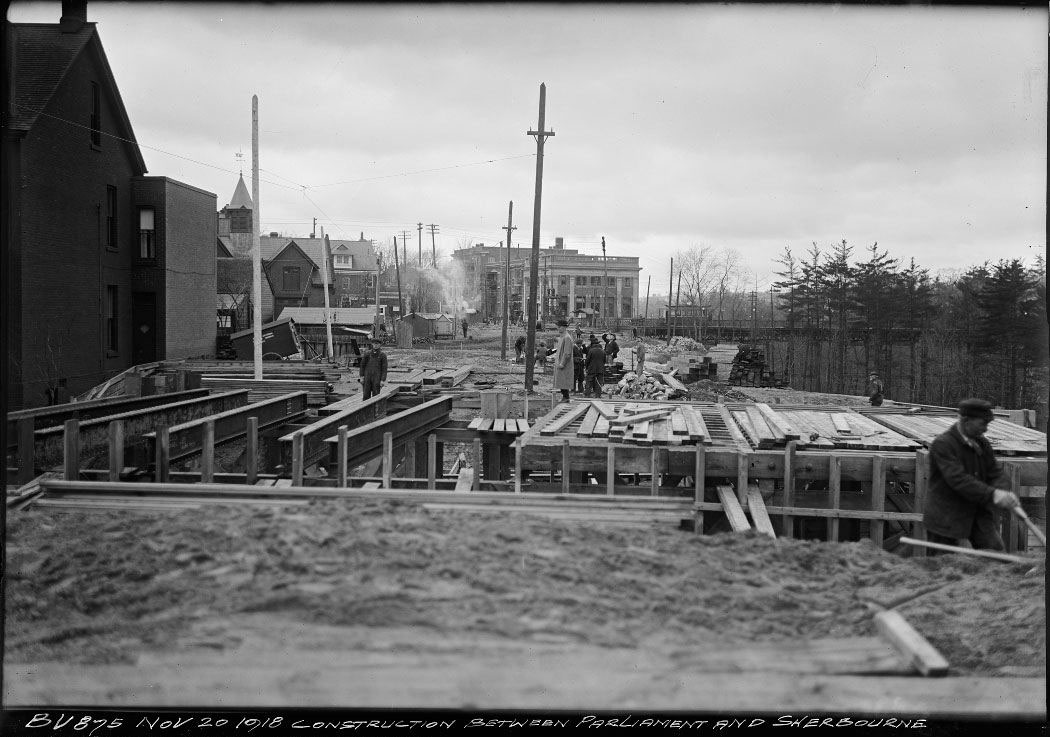
This view is looking west from the corner of Parliament Street. The railing of the Rosedale Section is seen at the right of the image, and the backs of the houses on Howard Street are on the left. The streetcar tracks are being installed and the men high up on the poles are stringing the overhead wires. In the photo on the right, the Dominion Bank at the north-west corner of Bloor and Sherbourne streets (which still exists) is seen in the middle distance, and the iron bridge that crossed the Rosedale Valley as North Sherbourne Street is just visible. The workers are building the underpass for Glen Road through the embankment.
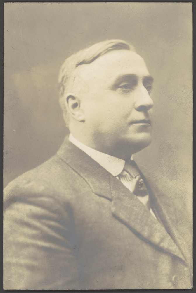
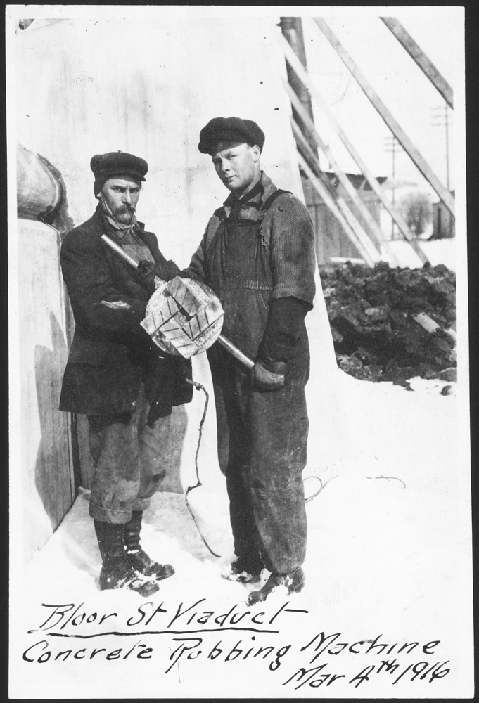
Much of the technical information of about the construction of the viaduct can be found in an extremely useful article that was written in 1919 by Thomas Taylor, who was the Designing and Construction Engineer for the project. Mr. Taylor’s family donated materials to the Archives relating to the viaduct, including some wonderful photographs which focus on the construction workers. The following images are a selection from the Thomas Taylor fonds.
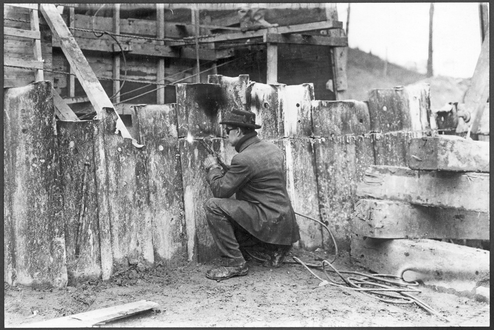
The worker is using an acetylene torch to cut through a section of steel sheet piling. The goggles protect his eyes, but his clothes seem somewhat inappropriate for the task.
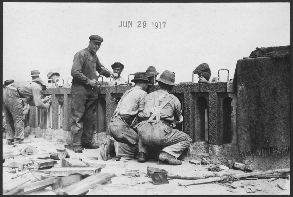
Much care was taken with the parapet of the viaduct to give it a suitable level of ornamentation. Unlike the rest of the concrete on the bridge, the parapet and railings had a scrubbed finish, which provided a rougher surface texture with exposed particles of red granite.
Back to introduction
Next page - The Viaduct Opens